Type 450 is a Class 1, composite screened, three-core trailing cable — the
highest-voltage open-cut trailing cable in AS/NZS 2802:2000, rated up to 33/33 kV. Its
construction differs fundamentally from lower-voltage types: three individually
composite-screened power cores are laid up around a plain elastomer centre filler (no
cradle separator, no central pilot). The outer interstices hold two elastomer-covered earth
conductors, one elastomer-covered pilot conductor, and six shaped elastomer fillers —
giving Type 450 its characteristic cross-section.
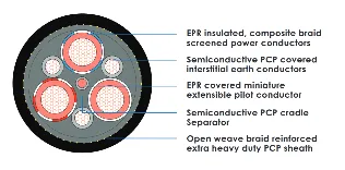
As a Class 1 cable, power core insulation is XR-EP-90 (high-grade EPR) and the outer
sheath is XHD-85-PCP or XHD-90-CSP/CPE with mandatory internal polyethylene
terephthalate yarn reinforcement. Each power core carries a composite screen (braid of
tinned Cu wire interwoven with PET yarn) plus a semiconductive tape over the screen.
Screen damage at 22–33 kV from bending under load: Composite braid screen is designed for trailing flexibility; braid coverage ≥80% maintained per AS/NZS 2802 Cl. 12.4.4. Mandatory sheath reinforcement (PET yarn) limits jacket damage from mechanical impact.
Insulation tracking at 33 kV: R-EP-90 triple extrusion with bonded conductor and insulation screens eliminates interface voids that initiate partial discharge. ti = 10.5 mm at 33 kV provides substantial dielectric margin.
Earth/pilot conductor damage in high-movement applications: Interstitial conductors and six shaped elastomer fillers distribute mechanical stress; covering thickness is set so each conductor touches both adjacent power cores and the circumscribing circle, ensuring mechanical stability during flex cycles.
USE WHEN: There are many variations of passages of ipsum available...
Open cut trailing supply at 3.3–33 kV (Class 1) where a single pilot circuit and two earth conductors in the interstitial positions are sufficient. Highest-voltage trailing cable in AS/NZS 2802DO NOT USE WHEN: Where a reduced pilot conductor is acceptable (use Type 451). Where semiconductive screening (not composite) is required (use Type 455). At 1.1 kV —use Class 2 types.
AS/NZS 2802:2000
AS/NZS 1125
AS/NZS 3808
CLASS 1
450.3 — 3.3/3.3 KV
450.6 — 6.6/6.6 KV
450.11 — 11/11 KV
450.22 — 22/22 KV
450.33 — 33/33 KV
Flame retardant and self-extinguishing per AS/NZS 2802. XHD-85-PCP or XHD-90-CSP/CPE sheath exceeds Class 2 sheath performance — extra heavy-duty compound formulation provides superior ignition resistance, flame propagation resistance and mechanical integrity under fire conditions.
| Oils & Hydraulic Fluids | Excellent (XHD sheath) |
| Acids & Alkalis | Excellent |
| UV / Ozone | Excellent |
| Abrasion | Superior (XHD vs HD) |
| Water Immersion | Suitable |
| Type | Voltage | Size Range (mm2) |
|---|---|---|
| 450.3 | 3.3/3.3 kV | 16 – 300 |
| 450.6 | 6.6/6.6 kV | 16 – 300 |
| 450.11 | 11/11 kV | 25 – 300 |
| 450.22 | 22/22 kV | 35 – 300 |
| 450.33 | 33/33 kV | 50 – 300 |
† Sizes beyond AS/NZS 2802:2000 Table 17 manufactured to Znergy Engineering specification — confirm dimensions prior to ordering.
Type 450 uses a full-size interstitial pilot; Type 451 uses a reduced-size pilot in the same position — choose 451 where pilot current demands are lower and a smaller conductor cross-section is acceptable. For semiconductive (not composite) screening at 3.3–11 kV, choose Type 455. For voltages ≤22 kV with individual core screening, choose Type 441 (Class 1)
| Property | Specification |
|---|---|
| Min. bend radius (trailing) | 8 × OD |
| Min. bend radius (fixed) | 10 × OD |
| Conductor stranding | Rope-lay, Class 5 flexible (AS/NZS 1125) |
| Sheath | XHD-85-PCP or XHD-90-CSP/CPE (Class 1) |
| Sheath reinforcement | Mandatory — PET yarn, open-weave braid (AS/NZS 2802 Cl. 23.1.2) |
| Approx. OD range | 42.0 mm (16 mm2/3.3 kV) to 105.1 mm (300 mm2/11 kV) |
| Note — 33 kV sizes | Only 50 and 70 mm2 tabulated in AS/NZS 2802:2000 Table 17 |
Standard: AS/NZS 2802:2000 — Class 1 (Table 17)
Configuration: 3C + 2E interstitial + 1P interstitial + 6 shaped elastomer fillers
Centre: Plain elastomer centre filler (no cradle separator, no central pilot)
Conductor: Tinned annealed Cu, rope-lay (Class 5 flex) per AS/NZS 1125
Conductor Screen: Extruded semiconductive elastomer per core (Class 1)
Insulation: XR-EP-90 (Class 1 high-grade EPR) per AS/NZS 3808
Insulation screen: Semiconductive elastomer + composite braid per core
SC tape: Semiconductive tape over composite screen per core
Earth conductors: 2 × interstitial, tinned Cu, elastomer covered
Pilot conductor: 1 × interstitial, tinned Cu, elastomer covered (full size)
Shaped fillers: 6 × elastomer fillers in remaining outer interstitial spaces
Core assembly tape: Textile tape over core assembly (where separate interstitial fillers used)
Outer sheath: XHD-85-PCP or XHD-90-CSP/CPE — reinforced with PET yarn (mandatory) per AS/NZS 2802 Cl. 23.1.2
| Parameter | Value |
|---|---|
| Voltage rating | 3.3/3.3 kV to 33/33 kV (U0/U) — Class 1 |
| Max conductor temp | 90 °C continuous |
| Insulation material | R-EP-90 (Class 1 — high grade) |
| ti range | 2.2 mm (3.3 kV) to 10.5 mm (33 kV) |
| Screen type | Composite Cu braid + SC tape per core |
| Triple extrusion | Required at 3.3 kV and above (Class 1) |
| Symmetry | Electrically symmetrical design |
| Sheath | XHD — reinforced (mandatory per AS/NZS 2802 Cl. 23.1.2) |
ZNE[size]-450.[voltage]
e.g. ZNE95-450.11 = 95 mm2 Type 450 at 11/11 kV (Class 1)
| Normal Operation | Emergency | Short Circuit |
|---|---|---|
| 90°C Conductor | 130°C | 250°C (5 s max) |
Znergy is an Australian-based cable engineering and manufacturing group supplying power cable solutions to mining, infrastructure, and industrial markets
© 2026 All Rights Reserved by Znergy Cable | Designed By FODUU