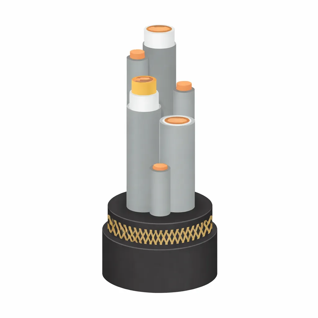
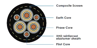
Type 451 is a Class 1, composite screened, three-core trailing cable for open cut and
surface mining at 3.3–33 kV. It shares the same power core architecture as Type 450 —
centre filler, three individually composite-screened XR-EP-90 insulated power cores, two
interstitial earth conductors, and a reinforced XHD outer sheath — but differs in one key
respect: the pilot conductor is reduced in cross-section compared to Type 450.
The reduced pilot (75/0.40 mm or 99/0.40 mm depending on size) is sized to carry pilot
protection and monitoring signals only, not the current capacity of the full-size pilot in
Type 450. Where the outer interstices are not fully occupied by the three covered
conductors, the outer sheath fills the remaining space directly — no separate shaped
elastomer fillers are specified for Type 451 (unlike Type 450).
Both earth conductors and the pilot conductor carry separate specifications in AS/NZS
2802:2000 Table 18, unlike Type 450 where a single combined entry covers all three
interstitial positions.
Pilot conductor overload in high-signal-current applications: Type 451 uses a reduced pilot — verify pilot current requirements against conductor CSA before specifying. Where higher pilot current capacity is needed, use Type 450.
Screen fatigue in long trailing cycles: Composite braid screen (tinned Cu wire interwoven with PET yarn) with ≥80%coverage per AS/NZS 2802 Cl. 12.4.4 maintains earth fault detection integrity throughout service life.
Sheath wear at drum flanges: Mandatory PET yarn reinforcement within the XHD sheath (Cl. 23.1.2) provides mechanical protection at high-stress contact points
Use When: Open cut trailing supply at 3.3–33 kV (Class 1) where pilot current demands are low and a reduced pilot conductor cross-section is acceptable. Cost-effective alternative to Type 450 where full pilot CSA is not required.
DO NOT USE WHEN: Where pilot must carry significant current (use Type 450). Where semiconductive (not composite) screening is required (use Type 455). At voltages above 33 kV.
AS/NZS 2802:2000
AS/NZS 1125
AS/NZS 3808
CLASS 1
451.3 — 3.3/3.3 KV
451.6 — 6.6/6.6 KV
451.11 — 11/11 KV
451.22 — 22/22 KV
451.33 — 33/33 KV
Flame retardant and self-extinguishing per AS/NZS 2802. XHD-85-PCP or XHD-90-CSP/CPE extra heavy-duty sheath provides superior ignition resistance and flame propagation performance over Class 2 cables.
| Oils & Hydraulic Fluids | Excellent (XHD sheath) |
| Acids & Alkalis | Excellent |
| Excellent | Excellent |
| Abrasion | Superior (XHD vs HD) |
| Water Immersion | Suitable |
| Type | Voltage | Size Range (mm2) |
|---|---|---|
| 451.3 | 3.3/3.3 kV | 16 – 300 |
| 451.6 | 6.6/6.6 kV | 16 – 300 |
| 451.11 | 11/11 kV | 25 – 300 |
| 451.22 | 22/22 kV | 35 – 300 |
| 451.33 | 33/33 kV | 50 – 300 |
† Sizes beyond AS/NZS 2802:2000 Table 18 manufactured to Znergy Engineering specification — confirm dimensions prior to ordering.
Type 451 is the reduced-pilot variant of Type 450 — same power core and sheath construction, smaller pilot conductor. Choose Type 450 where a full-size interstitial pilot is needed. Choose Type 455 where semiconductive (not composite) screening is preferred at 3.3–11 kV. Choose Type 441 (Class 1) where individually screened power cores are required at 3.3–22 kV.
| Property | Specification |
|---|---|
| Min. bend radius (trailing) | 8 × OD |
| Min. bend radius (fixed) | 10 × OD |
| Conductor stranding | Rope-lay, Class 5 flexible (AS/NZS 1125) |
| Sheath | XHD-85-PCP or XHD-90-CSP/CPE (Class 1) |
| Sheath reinforcement | Mandatory — PET yarn, open-weave braid (AS/NZS 2802 Cl. 23.1.2) |
| Approx. OD range | 42.0 mm (16 mm2/3.3 kV) to 100.2 mm (70 mm2/33 kV) |
Standard AS/NZS 2802:2000 — Class 1 (Table 18)
Configuration: 3C + 2E interstitial + 1 reduced pilot interstitial
Centre: Plain elastomer centre filler (no cradle separator)
Conductor: Tinned annealed Cu, rope-lay (Class 5 flex) per AS/NZS 1125
Conductor Screen: Extruded semiconductive elastomer per core (Class 1)
Insulation: XR-EP-90 (Class 1 high-grade EPR) per AS/NZS 3808
Insulation Screen: SC elastomer + composite braid per core; bonded at 6.6 kV+
SC tape: Semiconductive tape over composite screen per core
Earth conductors: 2 × interstitial, tinned Cu, elastomer covered
Pilot conductor: 1 × interstitial, tinned Cu, elastomer covered —reduced CSA
Interstitial fillers: Remaining outer interstice space filled by outer sheath directly
Core assembly tape: Textile tape where separate fillers are used (optional)
Outer sheath: XHD-85-PCP or XHD-90-CSP/CPE — reinforced with PET yarn (mandatory) per AS/NZS 2802 Cl. 23.1.2
| Parameter | Value |
|---|---|
| Voltage rating | 3.3/3.3 kV to 33/33 kV (U0/U) — Class 1 |
| Max conductor temp | 90 °C continuous |
| Insulation material | XR-EP-90 (Class 1 — high grade) |
| ti range | 2.2 mm (3.3 kV) to 10.5 mm (33 kV) |
| Screen type | Composite Cu braid + SC tape per core |
| Triple extrusion | Reduced CSA — 75/0.40 or 99/0.40 per Table 18 |
| Sheath | XHD — reinforced (mandatory per AS/NZS 2802 Cl. 23.1.2) |
ZNE[size]-451.[voltage]
e.g. ZNE95-451.11 = 95 mm2 Type 451 at 11/11 kV (Class 1)
| Normal Operation | Emergency | Short Circuit |
|---|---|---|
| 90°C Conductor | 130°C | 250°C (5 s max) |
Znergy is an Australian-based cable engineering and manufacturing group supplying power cable solutions to mining, infrastructure, and industrial markets
© 2026 All Rights Reserved by Znergy Cable | Designed By FODUU