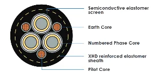
Type 455 is a Class 1, semiconductive screened, three-core trailing cable for open cut and surface mining at 3.3–11 kV. It is the ,SC-only screened counterpart to Type 450/451 — sharing the same interstitial conductor arrangement (centre filler, 2 earth + 1 pilot in outer interstices) but using a semiconductive elastomer insulation screen only, with no composite copper braid screen on the power cores
This makes Type 455 a lighter, more flexible construction suited to applications where the higher mechanical robustness of a composite screen is not required, and where the voltage does not exceed 11/11 kV. The absence of composite screen also means Type 455 does not carry a semiconductive tape over screen layer — the insulation screen is the outermost protection on each power core before lay-up
As a Class 1 cable, insulation is XR-EP-90 and the outer sheath is XHD-85-PCP or XHD-90-CSP/CPE with mandatory PET yarn reinforcement. Per AS/NZS 2802:2000 Table 19, earth and pilot conductors share the same combined specification.
SC screen damage in abrasive environments: Without a composite copper braid, the SC elastomer screen is the sole screening layer — sheath integrity is more critical. XHD reinforced sheath provides additional protection. Inspect sheath condition regularly in high-abrasion environments.
Partial discharge at screen interface: XR-EP-90 with extruded conductor and insulation screens (triple extrusion process at 3.3 kV+) eliminates interface voids. Bonded insulation screen at 3.3 kV and above per AS/NZS 2802 Cl. 12.2.
Earth/pilot conductor fatigue: Interstitial conductors and elastomer covering distribute bending stress during trailing cycles; covering thickness is set to ensure full contact with adjacent power cores per AS/NZS 2802 Cl. 15.2.
USE WHEN: Open cut trailing supply at 3.3–11 kV (Class 1) where semiconductive-only screening is acceptable and the composite braid of Types 450/451 is not required. Lighter and more flexible than equivalent composite-screened types.
DO NOT USE WHEN: At voltages above 11 kV (use Types 450/451). Where composite screen robustness is required (use Type 450/451). Underground coal mines (use Type 241/441). At 1.1 kV (use Class 2 types).
AS/NZS 2802:2000
AS/NZS 1125
AS/NZS 3808
CLASS 1
455.3 — 3.3/3.3 KV
455.6 — 6.6/6.6 KV
455.11 — 11/11 KV
Flame retardant and self-extinguishing per AS/NZS 2802. XHD-85-PCP or XHD-90-CSP/CPE extra heavy-duty sheath with mandatory PET yarn reinforcement provides superior fire performance over Class 2 equivalents.
| Oils & Hydraulic Fluids | Excellent (XHD sheath) |
| Acids & Alkalis | Excellent |
| UV / Ozone | Excellent |
| Abrasion | Very High (XHD sheath) |
| Water Immersion | Suitable |
| Type | Voltage | Size Range (mm2) |
|---|---|---|
| 455.3 | 3.3/3.3 kV | 16 – 300 |
| 455.6 | 6.6/6.6 kV | 16 – 300 |
| 455.11 | 11/11 kV | 25 – 300 |
† Sizes beyond AS/NZS 2802:2000 Table 19 manufactured to Znergy Engineering specification — confirm dimensions prior to ordering.
Type 455 is limited to 11 kV maximum — for 22–33 kV use Types 450 or 451. The key distinction from 450/451 is no composite braid — SC screen only. This produces a lighter, more flexible cable suitable for frequent-movement trailing at lower voltages. For individually screened power cores (per-phase fault detection) at 3.3–11 kV, use Type 441 (Class 1)
| Property | Specification |
|---|---|
| Min. bend radius (trailing) | 8 × OD |
| Min. bend radius (fixed) | 10 × OD |
| Conductor stranding | Rope-lay, Class 5 flexible (AS/NZS 1125) |
| Sheath | XHD-85-PCP or XHD-90-CSP/CPE (Class 1) |
| Sheath reinforcement | Mandatory — PET yarn, open-weave braid (AS/NZS 2802 Cl. 23.1.2) |
| Approx. OD range | 38.9 mm (16 mm2/3.3 kV) to 81.6 mm (150 mm2/11 kV) |
Standard AS/NZS 2802:2000 — Class 1 (Table 19)
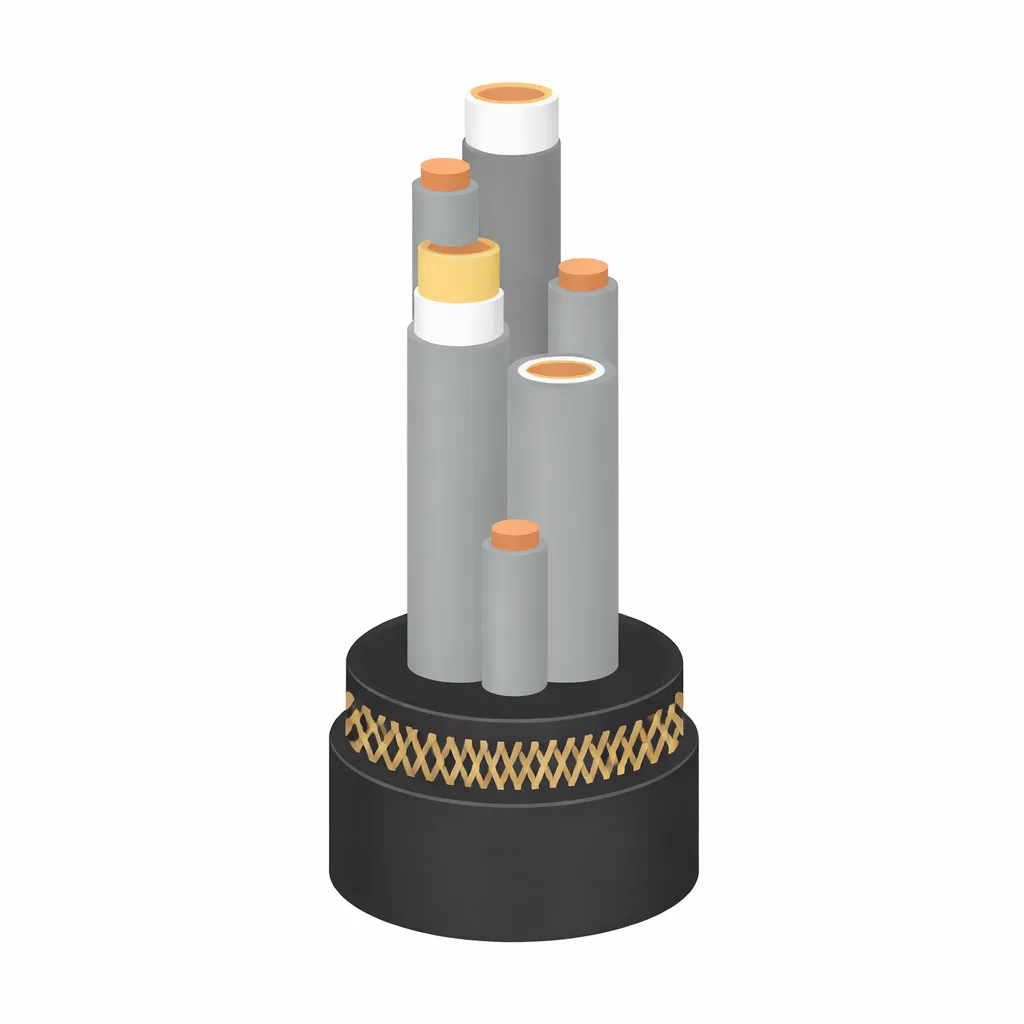
Configuration: 3C + 2E interstitial + 1P interstitial
Centre: Plain elastomer centre filler (no cradle separator)
Conductor: Tinned annealed Cu, rope-lay (Class 5 flex) per AS/NZS 1125
Conductor Screen: Extruded semiconductive elastomer per core (Class 1)
Insulation: XR-EP-90 (Class 1 high-grade EPR) per AS/NZS 3808
Insulation screen: Semiconductive elastomer only — no composite braid
Earth conductors: 2 × interstitial, tinned Cu, elastomer covered
Pilot conductor: 1 × interstitial, tinned Cu, elastomer covered —same spec as earths
Interstitial fillers: None specified — sheath fills remaining interstice space
Outer sheath: XHD-85-PCP or XHD-90-CSP/CPE — reinforced with PET yarn (mandatory) per AS/NZS 2802 Cl. 23.1.2
| Parameter | Value |
|---|---|
| Voltage rating | 3.3/3.3 kV to 11/11 kV (U0/U) — Class 1 |
| Max conductor temp | 90 °C continuous |
| Insulation material | XR-EP-90 (Class 1 — high grade) |
| ti range | 2.2 mm (3.3 kV) to 5.0 mm (11 kV) |
| Screen type | SC elastomer only — no composite braid, no SC tape |
| Triple extrusion | Required at 3.3 kV and above (Class 1) |
| Sheath | XHD — reinforced (mandatory per AS/NZS 2802 Cl. 23.1.2) |
| Max voltage | 11/11 kV — Type 455 not rated above this voltage |
ZNE[size]-455.[voltage]
e.g. ZNE95-455.6 = 95 mm2 Type 455 at 6.6/6.6 kV (Class 1)
| Feature | Type 455 | Types 450/451 |
|---|---|---|
| Screen | 3.3/3.3 kV | SC elastomer + composite Cu braid |
| SC tape over screen | None | Yes (mandatory) |
| Max voltage | 11/11 kV | 33/33 kV |
| Cable weight | Lighter | Heavier |
| Shaped fillers | None | 6 (Type 450 only) |
| Normal Operation | Emergency | Short Circuit |
|---|---|---|
| 90°C Conductor | 130°C | 250°C (5 s max) |
Znergy is an Australian-based cable engineering and manufacturing group supplying power cable solutions to mining, infrastructure, and industrial markets
© 2026 All Rights Reserved by Znergy Cable | Designed By FODUU